The design of the hull of marine vessels is laboratory. Elements of the ship's hull set
Ship classification
All vessels are subdivided into transport, fishing, service and support vessels and technical fleet vessels. Cargo ships are divided into two classes - dry cargo and tankers.
Universal dry-cargo vessels are designed for the carriage of general cargo.
General cargo is cargo in a package (in boxes, barrels, bags, etc.) or in separate places (machines, metal castings and rolled products, industrial equipment, etc.)
Rice. Universal vessel
Universal vessels are not adapted for the carriage of any particular type of cargo, which does not allow the maximum use of the vessel's capabilities. For this reason, cargo ships are being built and widely used in world shipping. specialized ships, on which the carrying capacity is better used and the time of stay in ports under cargo operations is significantly reduced. They are divided into the following main types: bulk carriers, container carriers, ro-ro carriers, lighter carriers, refrigerated, passenger ships and tankers, etc. All specialized ships have their own individual operational features, which require special additional training from the crew to acquire certain skills for the safe transportation of cargo, and also ensuring the safety of the crew and the ship during the voyage.
Refrigerated vessels (Reefers) - these are vessels with increased speed, designed for the transportation of perishable goods, mainly food, requiring the maintenance of a certain temperature regime in cargo spaces - holds. The cargo holds are thermally insulated, have special equipment and small hatches, and a refrigeration plant in the ship's refrigeration engine room is used to ensure the temperature regime.
Rice. Refrigerated vessel (Reefer)
Bulkers - these are ships that are adapted to a certain extent for the carriage in bulk of any bulk dry cargo. Bulk carriers usually do not have a cargo device, and all cargo operations are carried out by port facilities, and cargo holds hatches are made large for full mechanization.
Rice. Bulker
Container Ships - These are high-speed vessels designed for the transportation of various cargoes previously packed in special large-capacity containers of standard types. Cargo holds are divided by special guides into cells into which containers are loaded, and some of the containers are placed on the upper deck. Container ships usually do not have a cargo device, and cargo operations are carried out at specially equipped berths - container terminals. Some types of vessels are equipped with a special self-unloading device.
Rice. Container ship
Ro-Ro Ro-Ro ships - these are vessels with a horizontal loading method, used to transport laden trailers (trailers), wheeled vehicles, containers and packages. Vessels have one large hold and several decks. Cargo operations are carried out at the berth with the help of forklifts and platforms with tractors through the stern or bow ports (gates) of the vessel along special walkways - ramps, and the cargo is moved from deck to deck along internal ramps (a device for entering / exiting equipment) or using special elevators. lifts.
Rice. Roller "Ro-Ro"
Lighter Ships - these are ships where non-self-propelled barges - lighters are used as cargo units, the loading of which onto the ship in the port is carried out from the water, and unloading, respectively, onto the water.
Rice. Lighter ship
Passenger Ships- these are ships (Fig., intended for the carriage of passengers, in specially designed premises - passenger cabins, as well as luggage, mail, and some minor related cargo in special cargo compartments. They are divided into regular, cruise and local ships A distinctive feature is their high comfort and speed, as well as increased safety standards for passengers and the entire vessel as a whole.
Rice. passenger ship
Fishing vessel- a fishing vessel used for catching and primary processing of fish and other living objects of the aquatic industry. Fishing vessels include seiners, trawlers, longliners and others, differing in purpose, dimensions, type of fishing device and fish processing equipment, method of storing the catch.
Rice. Fishing vessel
Timber carrying vessel- a vessel for the transportation of timber cargo, including round timber and sawn timber in bulk, in packages and block packages. When transporting timber for the full loading of the vessel, a significant part of the cargo is taken to the upper deck (caravan). The deck on timber carriers is fenced with a high-strength bulwark and equipped with special devices for attaching the caravan: wooden or metal walls installed along the sides of the vessel, and transverse lashings.
Rice. Timber carrier
Sailing vessel- a vessel for the movement of which wind energy is used, which is converted with the help of sails. Sailing ships differ in the number of masts and the type of sailing equipment.
Rice. Sailing ships
Service and auxiliary vessels - ships for the logistics of the fleet and services organizing their operation. These include icebreakers, towing, rescue, diving, patrol, pilot boats, bunkering boats, etc.
Rice. Service vessel
Tankers - These are tankers designed for bulk transportation in special cargo spaces - tanks (containers) of liquid cargo. All cargo operations on tankers are carried out by a special cargo system, which consists of pumps and pipelines laid along the upper deck and in cargo tanks. Depending on the type of cargo carried, tankers are divided into:
tankers- these are tankers designed for bulk transportation in special cargo spaces - tanks (tanks) of liquid cargo, mainly oil products;
gas carriers (Liquefied Gas Tankers)- these are tankers designed for the transportation of natural and petroleum gases in a liquid state under pressure and (or) at low temperature, in specially designed cargo tanks of various types. Some types of ships have a refrigerated compartment;
chemical tankers- these are tankers designed for the transportation of liquid chemical cargo, the cargo system and tanks are made of special stainless steel, or covered with special acid-resistant materials.
The design of the hull is determined by the purpose of the ship and is characterized by the size, shape and material of the parts and parts of the hull, their mutual arrangement, methods of connection.
Rice. Internal structure of the ship a) dry cargo ship; b) tanker
1-forepeak; 2-cargo holds (tanks); 3-tween deck; 4-double bottom; 5-diptank;
6 engine room; 7-tunnel propeller shaft; 8-after peak; 9th;
10-medium superstructure; 11 cabins; 12-tank; 13-dry cargo hold; 14-pump department;
15 rubber dam
Consider the main elements of a small boat.
Frame- the main part of any vessel, consisting of a set (frame) and plating. The set is a combination of longitudinal and transverse braces that provide the body with rigidity and give it the appropriate shape.
bow of the ship- the forward part of the vessel.
Stern- back of the ship.
Board- the side of the body. Each ship has two sides - right and left. To determine the sides, you need to become facing towards the bow of the vessel, while the right side will be on the right, and the left side on the left.
Waterline- a theoretical or conditional line resulting from the intersection of the surface of the ship's hull with a horizontal plane or water level. Cargo waterline - the waterline in the presence on the vessel of the amount of cargo and passengers established for it. The load waterline is recommended to be painted with contrasting paint around the entire hull. It is not allowed to load the ship to a draft above the load waterline.
Draft- the size of the immersion in the water of the ship's hull. Distinguish between the draft of a loaded ship and an empty one. Draft is measured from the lower edge of the bottom of the vessel or from the edge of the propeller blade to the current waterline. Every driver needs to know exactly the draft of his vessel depending on the load, so that when sailing in shallow waters, the vessel does not run aground or the propeller is damaged.
Freeboard- the part of the side above the load waterline. Due to the fact that when the ship is properly loaded, the freeboard does not normally sink into the water, it is sometimes called a "dry board".
Minimum freeboard- the smallest distance from the effective waterline to the deck line or cutout in the transom at full displacement of the ship.
The main dimensions of the vessel and its elements
Rice. 2. The main dimensions of the vessel:
a) without permanently protruding parts;
b) with constantly protruding parts;
c) in the cross sections of the body.
The main dimensions of the vessel are length, width, depth and draft. (Fig. 2).
- Overall length(Lnb) - the distance measured in the horizontal plane between the extreme points of the bow and stern of the vessel, excluding protruding parts.
- Overall length(LGB) - the maximum length of the vessel, taking into account protruding parts.
- Structural length(Lkvl) - length , measured between the bow and stern perpendiculars of the design waterline. At the same time, constructive waterline(KVL) - the waterline taken as the basis for constructing a theoretical drawing and corresponding to the total displacement of the vessel obtained by preliminary calculation.
- Width(Vnb) - DWL distance, measured in the widest part of the ship, excluding protruding parts.
- Overall width(Bgb) - the maximum width of the vessel, taking into account protruding parts, such as fenders.
- Width at midship frame(B) - DWL distance in the widest part of the vessel.
- Board height(H) - vertical distance measured on the midship frame between the inner surfaces of the upper deck (at the side) and the horizontal keel.
- Draft (T) - the vertical distance measured from the DWL to the lower edge of the keel at the place of the deepest vessel. There is also a draft with the bow (Tn) and stern (Tk;). The difference between them is called trim D: Distinguish between the draft of a loaded ship and an empty one. Draft is measured from the lower edge of the bottom of the vessel or from the edge of the propeller blade to the current waterline. Every driver needs to know exactly the draft of his vessel depending on the load, so that when sailing in shallow waters, the vessel does not run aground or damage the propeller.
Body kit, dialing systems. Basic concepts and terms.
The design of the hull must ensure watertightness and sufficient strength of the vessel. The hull, experiencing the action of the forces of the ship's own weight and the forces of water pressure, which are unevenly distributed along the length, can get a bend.
The ability of a ship to resist bending loads is called longitudinal strength.
In addition to the longitudinal bending of the vessel, under the action of water pressure, cargo, mechanisms and other ship equipment, there is a local deformation of the bottom, sides and flooring in the transverse direction.
The ability of a vessel to withstand forces that cause transverse deformation of the hull is called transverse strength.
Under excessive loads, the body may break. To prevent this from happening, the sheathing sheets are reinforced with a set - longitudinal and transverse beams.
The set of longitudinal and transverse beams that form the frame of the vessel is called ship kit corps.
The ship hull set, being a frame, is made of the most durable materials. It consists of longitudinal and transverse bonds. The main longitudinal connection is the keel, which is installed in the centreline of the ship. For wooden ships, it is a strong bar made of strong wood (oak, ash, etc.), and for metal ships it is a thickened strip of metal. In the bow of the vessel, a stem is attached directly to the keel. This is a bar bent upwards or a metal square, which is a continuation of the keel. A similar beam or square, but installed in the stern, is called a sternpost. In wooden ships, the stem and sternpost, as well as the keel, are made of durable wood. The stern of motorized boats usually ends with a transom. It is a frame made of hardwood bars, sheathed on the outside with boards or plywood. The transom is securely attached to the keel. For boats with outboard motors, transoms must be of increased strength, as they perceive the thrust of the propeller and the vibration of a running engine.
The longitudinal and transverse beams of the ship's set are arranged in a certain sequence, called the set system. Depending on the ratio of longitudinal and transverse beams dialing systems subdivided into: longitudinal, transverse and combined (Fig. 3)
.

Set elements
Longitudinal elements (beams) ships are:
keel - the longitudinal beam of the bottom set, passing in the middle of the width of the vessel;
Stringers - longitudinal beams of the bottom and side set. Depending on the location, they are: side, bottom and zygomatic;
Carlings - longitudinal deck beams;
Longitudinal stiffeners - longitudinal beams of a smaller profile than stringers and carlings. According to their location, they are called below-deck, side or bottom and provide rigidity to the outer skin and deck plating during longitudinal bending.
Transverse elements (beams) of the vessel:
Flora - transverse beams of the bottom set, stretching from side to side. They are waterproof, solid and bracketed;
Frames - vertical beams of the board set, which are connected at the bottom with the floors with the help of brackets. Knit is a piece of triangular sheet steel used to connect various parts of the hull. On small vessels (boats), floors may be absent and the frames are integral beams of the side and bottom set.
Beams - transverse beams of the underdeck set, passing from side to side. If there are cutouts in the deck, the beams are cut and are called half-beams. At one end they are connected to the frame, and at the other end they are attached to the massive coaming, which borders the cutout in the deck, in order to compensate for the weakening of the deck ceiling by cutouts.

On the rice. 4 the simplest arrangement of the hull of a small vessel is shown with an indication of the main elements of the set, and in fig. 5 a more complete set of wooden motorboat hulls is presented.
Vessel frames are numbered from bow to stern. The distance between the frames is called space. Vertical, free-standing racks of round or other section are called pillers. Pillers serve to reinforce the deck and in its lower part rests against the intersections of floors (frames - on small ships) with bottom longitudinal beams (keel, stringer, keelson), and in the upper part - beams with carlings. Piller installation is shown in rice. 6.
On small motorized vessels (unlike large vessels), fenders are installed inside the hull. The top edge of the beam must be flush with the top edge of the topmost cladding chord. Both fenders (right and left sides) are bent along the contours of the ship's hull and attached to each frame and beam with screws with a diameter of 4-8 mm or bolts. In the nose, the fenders are connected to each other and to the stem with a square, called a breshtuk. The stern branches of the fenders are attached to the transom frame and transom sheathing with metal or oak knots.
The hull of a motor vessel is usually divided into three compartments by special waterproof bulkheads. The fore compartment is called the forepeak, the middle one is the working compartment, and the aft compartment is called the afterpeak.
On fig. 8 shows a section of the boat to explain the main names of its hull and superstructures.

Fig. 8 Section of the boat - 1 - rudder blade, 2 - helmport, 3 - sector-type tiller, 4 - transom, 5 - gas exhaust hole, 6 - deck flooring, 7 - fender, 8 - air intake grille 9 steps, 10 - stern flagpole, // - klotik flagpole, 12—stern signal light, 13—air intake shaft, 14—bulwark, 15—cockpit platform 16—zadrayka, 17—rail (railway), 18—bulwark door, 19—hatch cover, 20—handrail, 21—hatch coaming engine compartment, 22 - roof of the wheelhouse, 23 - helmsman's seat, 24 - steering wheel, 25 - carlings 26 - side signal (distinctive) light, 27 - top signal light, 28 - mast key, 29 - ship control panel, 30 - beam , 31 mast, 32 - mast mounting cushion, 33 - cockpit (cabin) roof, 34 - watertight bulkhead, 35 - mooring duck, 36 - bale bar, 37 - hatch coaming 38 - neck (hole in the bulkhead), 39 beams, 40 - ram bulkhead, 41-frontal strut of the cockpit, 42-carlings of the cockpit, 43 - coaming of the cockpit, 44 - side stand of the cockpit, 45 bulkhead, 46 - wall cockpit, 47—cheekbone angle, 48—watertight bulkhead, 49—side stringer 50—engine foundation, 51—half beam, 52—cockpit coaming, 53—afterpeak bulkhead 54—stern tube, 55—propeller shaft bracket 56—propeller propeller
Outer cladding. The outer plating of the vessel ensures the watertightness of the hull and at the same time participates in ensuring the longitudinal and local strength of the vessel.
Deck flooring. The deck deck ensures the watertightness of the hull from above and is involved in ensuring the longitudinal and local strength of the vessel.
Bulwark and railing. On sea, river and modern pleasure craft, to protect people from falling overboard, open decks have a bulwark or railing.
Superstructures and cabins. Superstructures are all enclosed spaces located above the upper deck from side to side. The bow superstructure is called the tank, the stern superstructure is called the poop. The middle superstructure does not have a special name.
Hydrofoils
Hydrofoils can still be found on almost every river, reservoir and sea. These are passenger motor ships, service boats, motor boats, the designs of which are developed by the navigators themselves.
The speed of hydrofoil ships is achieved mainly due to a decrease in water resistance to the movement of the ship's hull. In such vessels, the hull does not touch the water surface when moving. This happens as a result of the lifting force of the wings, reinforced under the hull, which, during the course, raises the ship above the water and keeps it in this state as long as the ship moves at a sufficient speed. Since in this case only wings, props, propeller shaft and propeller are in the water, and their total area is significantly less area hull, then the resistance of water to the movement of the vessel will be much less.
The principle of operation of the hydrofoil can be seen in the diagram (Fig. 9). When moving in the water of any body, the water resistance force R acts on it, directed in the direction opposite to the movement.
Since the wing profile has an asymmetric shape and, moreover, when the ship is moving, the wing is located relative to the flow at a certain angle a, called the angle of attack, then the total force R acting on the wing will deviate from the direction of movement and will be directed relative to it at an angle . This force can be decomposed into two components: perpendicular to the direction of motion Y and parallel to the direction of motion X. The Y component is called lift because it tends to lift the wing. The X component is called drag because it opposes the forward motion of the wing. The emergence of lift is associated with the formation of a circulation flow near the wing, which, superimposed on the main flow, accelerates the movement of water above the wing and slows it down under the wing. In this regard, according to Bernoulli's law, above the wing, where the flow rate is increased, the pressure decreases, and under the wing, where the flow rate is reduced, it increases.
|
|
The greater the speed of the oncoming flow, the greater will be the lift and drag. These forces also depend on the shape of the wing profile and on the angle of attack. With an increase in the angle of attack a, the lift force first increases and at a certain value, called the critical angle of attack acre, reaches its maximum value. With a further increase in a, the lift force decreases, which is associated with the separation of the flow from the upper surface of the wing. The force of drag increases continuously with increasing angle of attack. |
|
Fig 9 Forces acting on the wing profile |
With a small angle of attack of the hydrofoil, the ship will not be able to get on the wings due to insufficient lift, and with an overestimated angle of attack, due to high drag. |

It is customary to evaluate the perfection of a wing by a value called the quality of the wing and representing the ratio of lift to drag.
Usually, the reasonable speeds of ships with a displacement of 0.5-2 tons, equipped with hydrofoils, are in the range of 40-70 km/h. At ship speeds below 40 km/h, the wing device is very bulky and heavy; at speeds above 70 km / h, cavitation occurs on the wings, the movement becomes unstable.
In the wing mode, the mass of the vessel is perceived by the lifting force of the bow and stern wings, and the load is most often distributed between them equally. To exclude the negative effect of the bow wing on the aft distance between them, there should be at least 12-15 wing chords.
On small ships, various hydrofoil systems are used, the most common of which are shown in Fig. 10. The predominant distribution of them for river vessels received lightly submerged hydrofoils. The immersion depth of the bow wing of this design is 15-20% of its chord, the stern wing is 20-25%, the height of the hull of small boats above the water is 0.1-0.5 m with a running trim to the stern of 1.5-2.5 °.
A lightly submerged wing (Fig. 10, a) has a high hydrodynamic quality, so the necessary lift force is provided with relatively small areas. A significant drawback of such a wing, however, is low seaworthiness: in waves, the wings can be exposed, which causes hard impacts, since the entire wing area immediately comes into contact with water. In waves, a ship with lightly submerged wings experiences strong vibrations and often breaks off the wing regime.
The seaworthiness of vessels on lightly submerged wings can be partially increased by installing additional load-bearing elements fixed under the main bow wing (Fig. 10, b), the location of the keel section - "gull" in the middle part of the wing (Fig.-10, c), additional planes on the wing struts.


Fig. 10 Schemes of hydrofoils used on small-sized motor vessels: a - low-submerged wing, b - wing with an additional element, c - "seagull", d - wing crossing the water surface, e - trapezoidal wing with stabilizers, e split wing
The disadvantage in the first two cases is the increase in the overall draft of the vessel in sailing mode; in the third - an increase in resistance due to the "closure" of additional planes on the move, moreover, this scheme does not eliminate the "failure" of the wing when leaving the wave.
Wings crossing the surface of the water (Fig. 10, d, e) provide higher seaworthiness and, in addition, have the property of self-regulation when the load changes over a wide range. Movement stabilization is carried out as a result of a change in the submerged area of the wing. Due to the large immersion, these wings are less susceptible to wave disturbances that decay with increasing depth. The lifting force on the wings crossing the surface of the water in rough conditions changes smoothly, without loss of stability. Due to the inclined parts of the wing, the vessel has increased stability - when heeling, this section enters the water and the lifting force created on it restores the vessel to a straight position. To improve seaworthiness, the vessel can be equipped with different types of hydrofoils. For example, the bow wing is made to cross the surface of the water, and the stern wing is made in the form of a flat low-submerged wing.
In the practice of small shipbuilding, split nasal wings are also widespread (Fig. 10, e), which are easy to make folding. It should be noted that the hydrodynamic quality of such a wing is somewhat lower than that of a solid wing; therefore, a slightly higher engine power is required to obtain the same speed.
Classification of ship spaces
Ship spaces can be located inside the main hull, in superstructures and wheelhouses. The main hull, as already mentioned, is subdivided into compartments by watertight transverse bulkheads, and is limited from above by a bulkhead deck, which on multi-deck ships may not coincide with the upper deck. The extreme bow space is called the forepeak and is separated from the hold by a forepeak (ram) bulkhead. In collisions, the forepeak is damaged most often, and, as a rule, there is water ballast in it. There is also a chain (rope) box in the bow, in which the anchor chain is placed. The length of the forepeak is regulated by the Register Rules. The extreme aft compartment is the afterpeak, in which, in particular, the steering gear is located. One (or several - on high-speed vessels) compartment occupies the engine room. Most of the spaces on a cargo ship are cargo holds. If the ship has more than one deck, the cargo spaces are higher lower deck are called tween decks. Almost all ships are equipped with a double bottom, which protects cargo and other spaces from flooding when there are holes in the bottom. Double bottom compartments are used to store fuel supplies, as well as for water ballast, etc. On some ships, in addition to the double bottom, double sides are also made.
From other rooms in the main building we will name deep tanks - deep compartments for liquid cargo over a double bottom; vertical and horizontal cofferdams - narrow spaces bounded by two impenetrable bulkheads (decks, platforms) and isolating tanks for oil products from other spaces.
Superstructures at the extremities (forecastle and poop) not only reduce the flooding of the deck in waves, but also create a reserve of buoyancy that increases unsinkability. The superstructures can contain premises for various purposes: residential, office (departments of the main and auxiliary mechanisms, various equipment, workshops, administrative, etc.), public (cabin, canteens, restaurants, gym, swimming pool, library, etc.). ), special (fish factory, laboratories, helicopter hangar, etc.) and many others - consumer services, catering, medical facilities, supplies and supplies, etc. Decks in the superstructure are called the superstructure deck of the first tier, second, etc. ., counting from below (in the main body, the count goes, on the contrary, from top to bottom).
The location of the premises is depicted on the drawings of the general arrangement. The development of such drawings when designing a ship is a rather time-consuming and responsible job. Recently, thanks to computer technology and related software, it has been simplified. At the same time, it is necessary to ensure not only the required volumes and areas of each room, but also their relative position. For example, the crew and passenger quarters must be isolated from each other. The engine crew should be located near the engine room, the captain and his assistants - in the area of the wheelhouse. There are sanitary standards that regulate the size of residential and other premises (as well as, for example, noise and vibration levels in them).
Ship spaces are separated from each other by bulkheads (impermeable and permeable) and partitions - light structures, metal, including light alloys, wood, etc. Inside, many spaces are covered with insulation, lining; they may be finished. Insulation is very important for refrigerated (cooled) holds. Residential and public spaces are finished with decorative materials. Insulating and finishing materials should be, as far as possible, fire-resistant and not emitting toxic substances when burned, since fires are possible on ships, which pose a serious danger. It should not be thought that a fire on a ship surrounded by water is easy to extinguish. Fire on a ship can spread very quickly, often with the release of toxic gases, and when extinguishing it, there have been cases of capsizing ships due to hitting a large number water on high decks. A set of special measures is taken to detect fire, extinguish fire, and prevent its spread throughout the ship.
Why does a steel ship not sink, but is still able to carry significant loads and withstand the flooding of one, and sometimes two or three compartments, although the density of the steel from which the hull is made is almost 8 times greater than that of water? The reason is simple - the hull is a relatively thin shell, supported by a set - beams different directions and empty inside. The result is a fairly light, but strong structure that can withstand the loads acting on the ship in various operating conditions: during construction, loading or unloading, when sailing in waves, in ice, during repairs, in particular, when docking, in case of accidents. . Strength issues, including the loads acting on the ship, will be discussed in the next section. Here we will talk about the design of ships.
The main elements of the ship's hull can be considered plates of various orientations - horizontal (bottom, decks), vertical longitudinal (sides) and transverse (bulkheads), forming the ship's contours and ensuring its impenetrability. The sheets are stretched along the vessel and form belts. But unsupported plates will inevitably be crushed by water pressure, so they are reinforced with beams in both (along and across) or, more rarely, in one direction. The set of plates and the beams reinforcing them is called the floor (bottom, side, deck).
As a rule, one side of the floor is noticeably shorter than the other, and most of the reinforcing beams are oriented along the short side, which provides less weight for equal strength. These beams are called beams of the main direction (BGN). The distance between the BGN is usually assumed to be the same over a considerable distance and is called spacing (practical); at the extremities, the spacing often decreases. More powerful beams run along the long side, which support the BGN and are called cross braces (CS).
Depending on the orientation of the BGN, a distinction is made between the transverse and longitudinal systems of the overlap set. With a transverse system, the BGN are located in the plane of the frame, with a longitudinal system they are directed along the vessel. There is a checkered typing system, when he breaks the overlap into approximately square plates.
The framing system of the vessel as a whole is determined by the framing system of its floors. On small vessels, all floors, as a rule, are recruited according to the transverse system. It is more convenient in construction and provides higher local strength. On large ships, especially tankers, a longitudinal framing system is preferable, which allows to increase the overall longitudinal strength of the vessel and, very importantly, the stability of the plates (buckling of the plates is called their buckling during compression, accompanied by a loss of bearing capacity). In a large-tonnage tanker, the longitudinal size of the overlap (the distance between the transverse bulkheads) is almost always less than the transverse one, which makes the longitudinal system advantageous. The slab set system may be different for different slabs. For example, the deck and bottom (double bottom) can be typed along the longitudinal, and the sides - along the transverse system. Or a longitudinal system is used in the middle part, and a transverse system is used in the extremities. In such cases, one speaks of a mixed hull recruitment system.
With the transverse framing system of the vessel, its hull, elongated in the longitudinal direction, is similar to a set of rings of approximately rectangular shape. Each such ring is called a frame frame. The beams passing under the deck are called beams, along the board - frames (or side branches of the frames), in the double bottom - floors. Floors are waterproof (on the continuation of transverse bulkheads), solid (with cutouts to facilitate construction and for passage), bracketed (made of rectangular plates and stiffeners). The longitudinal beams (PS) of the deck are called carlings, the sides and bottoms are called side and bottom stringers, respectively. On ships that do not have a double bottom, the bottom stringers are called kilsons. Note that the term "deck stringer" refers to the deck belt immediately adjacent to the side. Sheerstrake - the upper belt of the board. In the DP, a vertical keel runs along the bottom, and the bottom sheet adjacent to it is called the horizontal keel. The deck stringer, sheerstrake, horizontal keel are made thicker than the belts adjacent to them. On ships of ice navigation, in addition, a thickened ice belt is made. Some ships have a tunnel keel formed by two vertical impermeable sheets located near the DP; various pipelines run inside it. On small vessels, a bar keel protruding downwards can be used. In the middle part along the length of the vessel, side (cheekbone) keels are very often installed, which serve as the simplest roll dampers. Beams of different directions as part of the frame frame are connected by small plates, the shape of which approaches a triangular one - with knees. In addition to the usual ones, frame frames are often made on ships, the profile of which is approximately the same as that of the PS; frame frames can be installed through 3 - 4 spacings. Hatch and other openings in decks are supported by coamings. On board above the upper deck is a bulwark. Bulkheads are supported by vertical posts and horizontal shelves.
On tankers, depending on their size, one, two or three longitudinal bulkheads are made to reduce the impact of liquid cargo during rolling. Longitudinal and transverse bulkheads can be corrugated, and the corrugations play the role of beams of the corresponding direction.
With a longitudinal system, the main set is called longitudinal stiffeners (deck, sides, bottom); cross-links are frame frames (and beams that are part of the frame frame). Reinforced longitudinal ties can also be used - carlings and stringers.
The design of the ship's hull is shown in several drawings. The structural midship frame shows the location and dimensions of the transverse braces (including the thickness of the outer plating and decking) in several characteristic sections along the length of the ship. The hull build depicts a hull recruitment scheme along its entire length. Stretching of the outer plating is a conditional unfolding of the outer plating of one side (sometimes two sides; in this case, the thickness of the sheets actually measured on each side is often applied to the stretch, indicating the chords, transverse and longitudinal set.
The hull design may include many other elements. We do not dwell on the design features of the ends, including posts, superstructures and deckhouses. It should be noted that decks and platforms often rely on vertical rods of tubular or box-shaped section - pillers. The mechanisms are installed on foundations that ensure the safe transfer of loads to the hull. In the stern of the ship there is often a deadwood - a narrow space elongated in the vertical direction, not occupied by a payload. Inside the deadwood there is a line of the shaft of a single-rotor vessel; at the outlet of the housing, a stern bearing of considerable length is made. In multi-propeller ships, the shafts exit the hull through mortars and are supported by brackets or fillets. To prevent water from entering the housing through the shaft outlets, special seals are used.
Until about the middle of the twentieth century. metal ships were made riveted. During the Second World War, a massive transition to welded shipbuilding began. At present, only a few riveted ships remain. Welding made it possible to significantly reduce the mass of the hull, simplify the construction technology, but required a radical redesign of the structures of various hull units and tightened the requirements for shipbuilding materials.
The design of the vessel as a whole and its individual components has a great influence on the strength and, consequently, the safety of navigation of the vessel. Therefore, the choice of thicknesses of plating, deck and double bottom decks, dimensions of reinforcing ties, etc. given serious attention. All these characteristics, as well as the design rules for various hull units, are regulated by the Register Rules and other industry regulations that summarize many years of ship operation experience, accident analysis, and scientific research results. When designing a vessel, these rules and regulations are taken into account. The introduction of new designs is accompanied by a thorough check of their performance in real operating conditions.
The hulls of civil marine vessels are made of relatively cheap low-carbon or low-alloy shipbuilding steel. Mild steel with a yield strength (the main material strength characteristic) of 235 MPa (1 MPa - megapascal \u003d 1 MN / m 2) is more often used for small and medium-sized ships; the main structures of large-tonnage vessels are made of stronger (with a yield strength of 300 - 400 MPa) low-alloy steels, with small additions of manganese, chromium, nickel, etc. For individual structures, stainless steels are used. In the hulls of large surface ships, and especially submarines, alloyed steels with a yield strength of up to about 1000 MPa are widely used. For ship superstructures, hulls of small ships, light (density about 2.7 t / m 3) aluminum-magnesium alloys are used. Some small boats are made of wood, fiberglass, etc. In domestic shipbuilding, including for the hulls of nuclear submarines, expensive, but very strong (at the level of the best shipbuilding steels) and relatively light (density about 4.5 t/m3) titanium alloys are used. For the hulls of many floating docks and individual ships, mostly non-self-propelled (for example, landing stages), reinforced concrete is used. Other materials are also used - rubber, plastics, copper alloys, paintwork, heat-insulating materials, etc.
Materials for ship hulls are used in the form of sheets and profiles (strip bulbs, angles, channels, I-beams, etc.) obtained by rolling; Welded profiles (tauri) are also widely used. Details of complex shape are obtained by casting or forging, light alloy profiles - by pressing (extrusion through profiled holes).
The design of the hull (Fig. 1.15) is determined by the purpose of the vessel and is characterized by the size, shape and material of parts and parts of the hull, their mutual arrangement, and connection methods.
The ship's hull is a complex engineering structure, which is constantly subjected to deformation during operation, especially when sailing in waves.

Rice. 1.15. The internal structure of the vessel:
a) dry cargo ship; b) tanker:
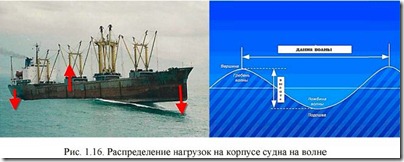
1 - forepeak; 2 - cargo holds (tanks); 3 - tween deck; 4 - double bottom; 5 - deep tank; 6 - engine room; 7 - propeller shaft tunnel; 8 - afterpeak; 9 - yut; 10 - middle superstructure; 11 - felling; 12 - tank; 13 - dry cargo hold; 14 - pumping room; 15 - rubber dam When the wave top passes through the middle of the ship, the hull experiences tension, while the bow and stern ends simultaneously hit the wave crests, the hull experiences compression. There is a deformation of the general bend, as a result of which the vessel may break (Fig. 1.16). The ability of a vessel to resist general bending is called overall longitudinal strength.

Rice. 1.16. Distribution of loads on the ship's hull on a wave
External forces, acting directly on the individual elements of the ship's hull, cause their local deformation. Therefore, the ship's hull must also have local strength.
In addition, the ship's hull must be watertight, which is ensured by the outer skin and upper deck plating, which are attached to the beams that form the set of the ship's hull ("skeleton" of the ship).
The set system is determined by the direction of most of the beams and is transverse, longitudinal and combined.
With a transverse framing system, the beams of the main direction will be: in the deck ceilings - beams, in the sides - frames, in the bottom - floras. Such a framing system is used on relatively short vessels (up to 120 meters in length) and is most advantageous on icebreakers and ice-going vessels, as it provides high hull resistance in case of transverse compression of the hull by ice. Midship frame - a frame located in the middle of the estimated length of the vessel.
With a longitudinal framing system in all floors in the middle part of the length of the hull, the beams of the main direction are located along the vessel. The ends of the vessel are recruited according to the transverse dialing system, because. at the extremities, the longitudinal system is not effective. The beams of the main direction in the middle bottom, side and deck ceilings are, respectively, the bottom, side and under-deck longitudinal stiffeners: stringers, carlings, keel. Cross-links are floors, frames and beams.
The use of a longitudinal system in the middle part of the length of the vessel allows for high longitudinal strength. Therefore, this system is used on long ships experiencing a large bending moment.

Rice. 1.17. Mixed ship set:
1 - keel; 2 - flooring of the second bottom; 3 - side stringers; 4 - beams; 5 - deck stringer; 6 - knit; 7 - sheerstrake; 8 - frame; 9 - side belt; 10 - zygomatic belt; 11 - floor; 12 - bottom stringer; 13 - keel belt

Rice. 1.18. Underdeck set:
1 - deck flooring; 2 - beams; 3 - carlings; 4 - pillers; 5 - beam knees; 6 - frames; 7 - side skin
With a combined framing system, the deck and bottom floors of the middle part of the hull length are nailed according to the longitudinal framing system, and the side ceilings in the middle part and all floors at the ends - according to the transverse framing system. Such a combination of flooring systems makes it possible to more rationally solve the issues of the overall longitudinal and local strength of the hull, as well as to ensure good stability of the deck and bottom sheets during their compression.
The combined recruitment system is used on large-capacity dry cargo ships and tankers. The mixed ship framing system is characterized by approximately the same distances between the longitudinal and transverse beams (Fig. 1.17). in the nasal and aft the set is fixed on the stem and stern that close the body.

Rice. 1.19. Bulk carrier hold

Rice. 1.20. Section of the tanker hull with a longitudinal framing system:
1, 2, 3 - below deck, side and bottom stiffeners; 4 - bottom knees; 5 - vertical keel; 6 - floor; 7 - longitudinal bulkheads; 8 - frame; 9 - frame beam; 11 - carlings; 12 - underdeck knees
The design of the hull (Fig. 1.15) is determined by the purpose of the vessel and is characterized by the size, shape and material of parts and parts of the hull, their mutual arrangement, and connection methods.
The ship's hull is a complex engineering structure, which is constantly subjected to deformation during operation, especially when sailing in waves. When the wave top passes through the middle of the ship, the hull experiences tension, while the bow and stern ends simultaneously hit the wave crests, the hull experiences compression. There is a deformation of the general bend, as a result of which the vessel may break (Fig. 1.16). The ability of a vessel to resist general bending is called overall longitudinal strength.
External forces, acting directly on the individual elements of the ship's hull, cause their local deformation. Therefore, the ship's hull must also have local strength.
In addition, the ship's hull must be watertight, which is ensured by the outer skin and upper deck plating, which are attached to the beams that form the set of the ship's hull ("skeleton" of the ship).
The set system is determined by the direction of most of the beams and is transverse, longitudinal and combined.
With a transverse framing system, the beams of the main direction will be: in the deck ceilings - beams, in the sides - frames, in the bottom - floras. Such a framing system is used on relatively short vessels (up to 120 meters in length) and is most advantageous on icebreakers and ice-going vessels, as it provides high hull resistance in case of transverse compression of the hull by ice. Midship frame - a frame located in the middle of the estimated length of the vessel.
With a longitudinal framing system in all floors in the middle part of the length of the hull, the beams of the main direction are located along the vessel. The ends of the vessel are recruited according to the transverse dialing system, because. at the extremities, the longitudinal system is not effective. Beams of the main direction in the middle bottom, side and deck ceilings are, respectively, bottom,
side and deck longitudinal stiffeners: stringers, carlings, keel. Cross-links are floors, frames and beams. The use of a longitudinal system in the middle part of the length of the vessel allows for high longitudinal strength. Therefore, this system is used on long ships experiencing a large bending moment.

With a combined framing system, deck and bottom floors in the middle part of the hull length are nailed using a longitudinal framing system, and side ceilings in the middle part and all floors at the ends are nailed using a transverse framing system. Such a combination of flooring systems makes it possible to more rationally solve the issues of the overall longitudinal and local strength of the hull, as well as to ensure good stability of the deck and bottom sheets during their compression. The combined recruitment system is used on large-capacity dry cargo ships and tankers. The mixed ship framing system is characterized by approximately the same distances between the longitudinal and transverse beams (Fig. 1.17). In the bow and stern parts, the set is fixed to the stem and stern that close the hull.